


2019 Honda Accord Fuse Box Diagrams
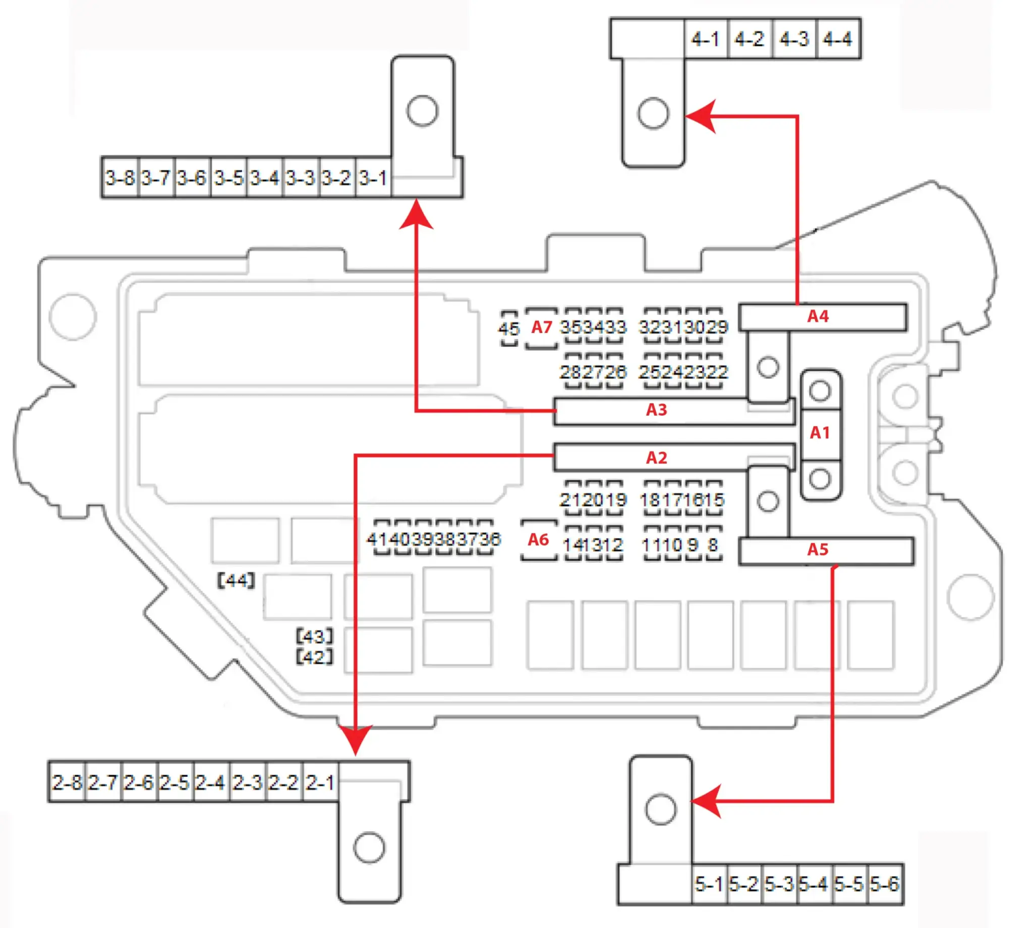
2019 Honda Accord Underhood Fuse Box Diagram
Fuse A1 125A Fuse Powers
A3-2 30A A/C condenser fan motor (via A/C condenser fan relay)
A3-3 30A PCM (START DIAG) (via starter cut relay 1 circuit (built into the relay circuit board)),
Starter (via starter cut relay 1 circuit and starter cut relay 2 circuit (built into the relay circuit board))
A3-5 40A Blower motor (via blower motor relay)
A3-7 60A No. B48 *, No. B49, No. B50, No. B53, and No. B54 fuses in the under-dash fuse/relay box, No. B51 and No. B52 fuses in the under-dash fuse/relay box (via power window relay), Power window relay. *: With head up display
A3-8 40A Rear window defogger (via rear window defogger relay)
A4-2 *1: With stereo amplifier
A4-4 60A No. B33 *1, No. B34 *2, No. B38 *1, No. B39 *2, No. B40 *1, No. B42, No. B43, and No. B44 *3 fuses in the under-dash fuse/relay box
*1: With stereo amplifier
*2: With heated steering wheel
*3: With rear seat heater
*4: With heated windshield wiper area
*5: With fog light
*6: With shutter grille
*7: With display audio
Fuse block A2 powers
A2-1 30A Via IG1A relay circuit (built into the relay circuit board):No. A40, No. A41, No. A42, and No. A43 fuses in the under-hood fuse/relay box, Body control module (IG1-A SIG)
A2-2 30A Not used
A2-3 40A VSA modulator-control unit (+B ABS/VSA FSR)
A2-4 40A Electric brake booster (+B BOOSTER MTR)
A2-5 60A No. B6, No. B9, No. B16, No. B17 *1, and No. B20 *2 fuses in the under-dash fuse/relay box
*1: With moonroof *2: With SBW shifter
A2-6 30A Not used
A2-7 70A EPS control unit (+B EPS)
A2-8 70A Not used
Fuse block A3 powers
A3-1 30A Not used
A3-2 30A A/C condenser fan motor (via A/C condenser fan relay)
A3-3 30A PCM (START DIAG) (via starter cut relay 1 circuit (built into the relay circuit board)),
Starter (via starter cut relay 1 circuit and starter cut relay 2 circuit (built into the relay circuit board))
A3-4 40A Not used
A3-5 40A Blower motor (via blower motor relay)
A3-6 30A Not used
A3-7 60A No. B48 *, No. B49, No. B50, No. B53, and No. B54 fuses in the under-dash fuse/relay box,
No. B51 and No. B52 fuses in the under-dash fuse/relay box (via power window relay),
Power window relay *: With head up display
A3-8 40A Rear window defogger (via rear window defogger relay)
Fuse block A4 powers
A4-1 30A Not used
A4-2* 70A No. B24 fuse in the under-dash fuse/relay box *With stereo amplifier
A4-3 40A Not used
A4-4 60A No. B33 *1, No. B34 *2, No. B38 *1, No. B39 *2, No. B40 *1, No. B42, No. B43, and No. B44 *3 fuses in the under-dash fuse/relay box — *1: With power seat
*2: With front passenger’s power seat, *3: With adaptive damper system,
Fuse block A5 powers
A5-1 40A Not used
A5-2 30A Radiator fan motor (via radiator fan relay)
A5-3 30A Relay control module (+B R/M2)
A5-4 40A VSA modulator-control unit (+B ABS/VSA MTR)
A5-5 30A Via IG1B relay circuit (built into the under-dash fuse/relay box):
Body control module (IG1-B SIG), No. B35, No. B36, No. B37, and No. B46 fuses in the under-dash fuse/relay box.
Via IG2 relay circuit (built into the under-dash fuse/relay box):
Body control module (IG2 SIG),
No. B14 and No. B15 fuses in the under-dash fuse/relay box
Via ACC relay circuit (built into the under-dash fuse/relay box):
No. B4 and No. B5 fuses in the under-dash fuse/relay box
A5-6 30A Windshield wiper control unit/motor
A6 30A Relay control module (+B R/M1)
A7 ――― Not used
A8 ――― Not used
A9 10A Via brake pedal position switch: Body control module (STOP SW), PCM (STOP SW)
Via brake light relay circuit (built into the relay circuit board): High mount brake light, Left brake light, Right brake light, VSA modulator-control unit (STOP LT)
Via brake pedal position switch and brake light relay circuit (built into the relay circuit board): High mount brake light, Left brake light, Right brake light,
VSA modulator-control unit (STOP LT)
A10 15A TCM (VB1) *1, TCM (+B) *2 *1: A/T *2: CVT
A11 20A PCM (INJ RLY OUT) (via injector relay)
A12* 10A TCM (VB2) *: A/T
A13 15A Injector relay, PGM-FI main relay 1 circuit (built into the relay circuit board) Via PGM-FI main relay 1 circuit (built into the relay circuit board): PGM-FI main relay 2 , PCM (FI MAIN RLY OUT)
A14* 10A TCM (VB3) *: A/T
A15 10A PCM (+B BACKUP FI-ECU)
A16 7.5A 12 volt battery sensor (BATT IR(BATT SNSR))
A17 15A PGM-FI subrelay circuit (built into the relay circuit board) Via PGM-FI subrelay circuit (built into the relay circuit board): No. A36, No. A37, and No. A38 fuses in the under-hood fuse/relay box, PCM (FI SUB RLY OUT)
A18 15A Ignition coil relay circuit (built into the relay circuit board),
Ignition coils (via ignition coil relay circuit (built into the relay circuit board))
A19 15A Body control module (+B HAZARD)
A20 ――― Not used
A21 ――― Not used
A22* 10A Heated steering wheel control unit (via heated steering wheel relay) *: With heated steering wheel
A23 ――― Not used
A24 15A Active noise cancellation unit (+B AUDIO), Audio unit (+B AUDIO) *1, Audio-navigation unit (+B AUDIO) *2, Center display unit, Telematics control unit (+B AUDIO) *3, USB charger unit (+B AUDIO) *4 *1: Without navigation, *2: With navigation
*3: With telematics, *4: With USB charger
A25* 20A Rear seat heater control unit (RR H/SEAT RLY SW) (via rear seat heater relay) *: With rear seat heater
A26* 15A Via heated windshield wiper area relay: Heated windshield wiper area,
Heated windshield wiper area switch
A27 10A Automatic lighting control unit-sensor *1*3, Automatic lighting/rain sensor *2, Body control module (+B BACK UP), CAN gateway (+B BACK UP) *4, Data link connector (DLC), Gauge control module (+B BACK UP), HomeLink ® unit (+B BACK UP) *5,
Power seat control unit (+B BACK UP) *6, Power window master switch (+B BACK UP),
Relay control module (+B BACK UP), Wireless charger (+B BACK UP) *7 *1: Without automatic wiper *2: With automatic wiper *3: With automatic lighting *4: With ACC
*5: With HomeLink ® *6: With DPMS *7: With wireless charger
A28 10A 12 volt battery sensor (+B HORN), Horn relay, Horn (high) (via horn relay),
Horn (low) (via horn relay)
A29* 10A Fog light relay, Left fog light (via fog light relay), Right fog light (via fog light relay) *: With fog light
A30* 7.5A Shutter grille *: With shutter grille
A31 10A A/C compressor clutch (via A/C compressor clutch relay)
A32 15A Windshield washer motor relay circuit (built into the relay circuit board),
Windshield washer motor (via windshield washer motor relay circuit (built into the relay circuit board))
A33 ――― Not used
A34 ――― Not used
A35*1 7.5A Audio unit (+B AUDIO SUB) *2, Audio-navigation unit (+B AUDIO SUB) *3
*1: With display audio, *2: Without navigation, *3: With navigation
A36 7.5A A/C condenser fan relay, Fan control relay, Turbocharger bypass control solenoid valve **: 2.0 L engine
A37 7.5A A/F sensor (sensor 1), EVAP canister purge valve, EVAP canister vent shut valve * *: USA and Canada models
A38 7.5A PCM (VB ACT)
A39 10A TCM (IG1)
A40 20A Body control module (IG1 FUEL PUMP), Electric steering lock (IG1 FUEL PUMP) *, Fuel tank unit (via PGM-FI main relay 2), No. A44 fuse in the under-hood fuse/relay box *: With electric steering lock
A41 7.5A Brake light relay circuit (built into the relay circuit board), EPS control unit (IG1 VSA/ABS) *1 (IG1 ABS/VSA) *2, VSA modulator-control unit (IG1 VSA/ABS) *1 (IG1 ABS/VSA) *2 *1: ’18 *2: ’19
A42 10A Left back-up light (via back-up light switch) *1, PCM (BKSWNC) (via brake pedal position switch), Right back-up light (via back-up light switch) *1,
Reverse lockout solenoid *1, SBW shifter control module (IG1 ACG) *2,
Secondary HO2S (sensor 2), Turbocharger bypass control solenoid valve *3 *1: M/T
*2: With SBW shifter, *3: 1.5 L engine,
A43 10A Stater cut relay 1 circuit (built into the relay circuit board),
Stater cut relay 2 circuit (built into the relay circuit board)
A44 7.5A PCM (IG1)
Posted on by Rick Muscoplat
#Honda #Accord #Fuse #Box #Diagram #Ricks #Free #Auto #Repair #Advice #Ricks #Free #Auto #Repair #Advice